
Integrated RTK drones promise centimetre-level accuracy. That promise is real, but it stops at the antenna. Here is everything that happens after.
The claim and what it actually means
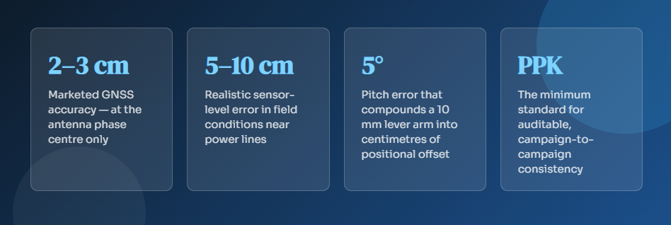
When a utility company purchases a drone with integrated RTK and reads “2–3 cm accuracy” in the specification sheet, the statement is technically accurate. It is also fundamentally incomplete. The accuracy figure describes the position of the GNSS antenna phase centre, a point several centimetres above the airframe. What matters operationally is the position of the sensor: a LiDAR scanner, a photogrammetric camera, or a multispectral imager. Between those two points lies a chain of error sources that no brochure mentions.
This matters enormously in utility inspection. Overhead line surveys, conductor sag modelling for dynamic line rating, and infrastructure change detection programmes all depend on positional truth at the sensor level. Understanding where the accuracy claim ends and where real-world error begins, is not an academic exercise. It directly determines whether your data is actionable or misleading.
Four hidden sources of error between antenna and sensor
1. The lever arm problem
The sensor is physically offset from the GNSS antenna. This offset — the lever arm — must be precisely known, along with the drone’s attitude at the moment of data capture, and the correct rotation from the body frame to the world frame. Manufacturers provide nominal lever arm values, but real units vary. A 10 mm lever arm error combined with just 5 degrees of pitch propagates into every single measurement. This is not a rounding problem. It is a systematic bias that compounds across an entire dataset.
2. IMU degradation near power lines
High-voltage conductors distort the local magnetic field. This corruption of the magnetic environment directly affects heading estimates from the IMU, the sensor the drone uses to determine its orientation in space. Add turbulence near structures, transient attitude states during wind gusts, and you have a situation where attitude accuracy in a 400 kV transmission corridor is significantly worse than any specification measured in an open test field. The drone’s positioning hardware was not characterised in your operating environment.
3. LiDAR has no self-correction mechanism
Photogrammetric workflows can partially recover from positional errors through bundle adjustment, a mathematical optimisation that redistributes residuals across a network of overlapping images and ground control. LiDAR has no equivalent. Every point is placed exactly where the geometry dictates: position plus attitude plus range plus boresight calibration. If any of those inputs carries error, that error is permanent and irrecoverable. When you are modelling conductor sag for dynamic line rating, a 5 cm noise floor is not a minor inconvenience. It invalidates the model.
4. Reference frame drift between campaigns
Two survey campaigns using different autonomous base positions and different IMU calibration states are not in the same reference frame. The difference between them looks precisely like structural deformation or infrastructure movement. Your change detection algorithm cannot distinguish genuine displacement from reference frame shift. Neither can a human analyst reviewing the outputs. This is the root cause of the noisy, unreliable results that erode confidence in drone-based monitoring programmes over time.
Why change detection programmes lose credibility
Change detection is one of the highest-value applications of UAV surveys in the utility sector. The ability to detect structural deformation, vegetation encroachmRTK drones ent, or hardware degradation between inspection cycles is commercially compelling. Yet many programmes produce results that operations teams do not trust, and eventually abandon.
The problem is almost never the drone hardware. It is almost never the processing software. The problem is the geodetic foundation — specifically, the absence of one. When each campaign floats in its own positional reference frame, determined by an autonomous base station that occupies a slightly different position each time, the delta between two campaigns contains real change plus reference frame noise. The two signals are inseparable. The data becomes uninterpretable.
Important distinction
Integrated RTK is necessary. It gives you a starting point of quality.
PPK makes it auditable. It ties your positions to a verifiable, reproducible reference. Neither replaces independent ground truth. These three layers work together; removing any one of them degrades the entire programme.
The Skyline Drones take
Integrated RTK is a significant step forward for UAV accuracy in utility inspection. It reduces the burden of field infrastructure and brings centimetre-level GNSS positioning within reach of operational teams. But the accuracy claim in the brochure describes one point in a long chain and every subsequent link in that chain must be managed with equal care.
Lever arm calibration. IMU behaviour in electromagnetically complex environments. Reference frame consistency across campaigns. Independent boresight verification for LiDAR. These are not advanced topics reserved for survey specialists. They are baseline requirements for any programme that intends to produce trustworthy, repeatable results.
If you are planning or expanding a UAV inspection programme in the utility sector and want to discuss how to build the right geodetic foundation, reach out to the Skyline Drones team.

